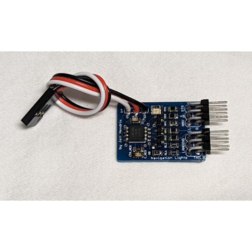
This is a small board that plugs into any servo channel and controls navigation lights
(if you have a cockpit gauge controller, you want to navigation light board that plugs into the controller)
The board is powered and controlled from a servo channel.
Board is powered by 5V. Board can be powered by 6V if trace is cut on the back and a diode is added.
The board has 5 settings controlled by servo channel.
Setting 1 - Sending a signal < 800us will turn all lights off
Setting 2 - signal between 800-1250us will turn on the navigation lights (3 position lights and beacon)
Setting 3 - signal between 1250-1750us will turn on navigation lights and strobes
Setting 4 - signal between 1750-1900us will turn on navigation and landing lights
Setting 5 - signal > 1900us will turn on navigation, strobes, and landing lights
Using the standard output from a 3 position switch (1000,1500, & 2000us) will give settings 2, 3, & 5
Sending no signal (just providing power) will output setting 5
Installing lights
I have installed lights a couple of ways.
One at least one of my planes, there were already channels to install the wiring
On some of my planes, I would make a shallow slice and push the wire into the slit and in some cases, run a thin bead of CA to close it up (also used hot glue)
Currently I've been cutting a tunnel into the foam. I took a bunch of brass tubes and sanded the ends to a point (see attached pictures) and put them in a drill (you can also do it by hand, it just takes longer). I would then cut the tunnel and feed the wire through. I would then solder the LEDs on and glue them into place, then attach the servo connector to the other side.
I've also attached a 2 pin connector and then plug the LED into it.
(see attached pictures of both of these methods)
Hooking up the board
If you hold the board with the microcontroller at the top, the LED pinouts are as follows
(see diagram below)
The center pin is +5 on all 4 connectors
The connectors on the left are for landing lights and the tail
The top one is Landing lights. The 2 outside pins are so you can run 2 landing lights
The bottom is the tail. The left pin is for a rotating beacon (simulated with PWM) and the right is the white position light.
The right connectors are for the wings. The top is the left wing and bottom is the right.
On both, the left pin is the colored position light and the right pin is the strobe.
All the outputs have a bias resistor (so you just connect an LED, no resistor needed) and all the resistors have been sized to provide ~20mA for each LED.
The reason there is a left and right connector is the red LED has a slightly different forward voltage so they should all be 20mA (but when I swap them around, I can't tell any difference in brightness).
If you want to drive incandescent lights, you can just jumper across the resistor and apply the full 5V to the bulb. All the resistors positions are labeled
The microcontroller is only rated for 5.5V, so if you want to plug the board into a 6V plug, turn the board over and cut the trace between 2 pads and solder on a diode. This should give about a .7 volt drop and keep it below 5.5V
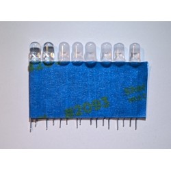
What LEDs to use.
You can supply your own LEDs or buy a set from me for $10.
I buy mine from https://superbrightleds.com/
Here are the part numbers of the LEDs I use (and the price for each)
1x Green RL5-G20-360 - .69 (right wing)
2x Red RL5-R10-360 - .49 (left wing, rotating beacon)
3x White RL5-W45-360 - 1.39 (wing strobes, tail position light)
2x white RL5-W10015 - .74 (landing lights)
(I just checked and they are out of green LEDs and when I asked them when they plan on getting more, they said they will not carry them any more).
I did find most of these LEDs on the following sites (just search for the part numbers)
http://www.ledlightcompare.com/
http://www.ledhutcompare.com/
http://www.smartbrightleds.com/
You can also use existing lights.
I installed the lighting kit for my binary and somehow killed the controller (I promise I wasn't poking around on it).
I replaced it with my board and it works great (see video above)
On another plane of mine, I bought some lights from aliexpress and was able to remove the existing drive circuits and connect them straight to my board and they work great.
Additional supplies
You will also need servo connectors and wire.
Here is the wire I've been using, this company also sells servo connectors
https://www.hansenhobbies.com/products/connectors/wire/servo_ec/sw_eclite_30_fu/


